TM-9-2320-361-34 - Page 381 of 764
TM 9-2320-361-34
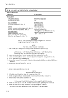
15-18. 115-VOLT AC RECEPTACLE REPLACEMENT
I
THIS TASK COVERS:
a. Removal
b. Installation
INITIAL SETUP
APPLICABLE MODELS
PERSONNEL REQUIRED
M185A3 and M109A3
Two
TEST EQUIPMENT
REFERENCES (TM)
Multimeter (Appendix B, Item 3)
TM 9-2320-361-10
TOOLS
TM 9-2320-361-20
TM 9-2320-361-34P
General mechanic’s tool kit (Appendix B, Item 1)
Tool kit, electrical (Appendix B, Item 2)
EQUIPMENT CONDITION
MATERIALS/PARTS
.
Parking brake set (TM 9-2320-361-10).
●
Battery ground cable disconnected
Gasket (Appendix F, Item 82)
(TM 9-2320-361-20).
Safety wire (Appendix C, Item 35)
Electrical tape (Appendix C, Item 26)
CAUTION
Use care when removing or installing wiring harness. Excessive
snagging or pulling may damage wires.
NOTE
Tag wires and terminals for installation.
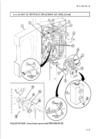
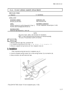
1. Slide handle (3) on safety switch box (2) to OFF position and open cover (5).
NOTE
●
Perform step 2 for M109A3 vehicles. Perform step 3 for M185A3 vehicles.
●
Safety wire must be attached to wires with electrical tape.
2. Loosen two screws (1) and remove two wires (4) from safety switch box (2).
3. Loosen two screws (7) and remove two wires (6) and wires (4) from safety switch box (2).
4. Attach safety wire (8) to two wires (4).
5. Remove four screws (11), receptacle (10), wires (4), and gasket (9) from van body (12). Discard
gasket (9).
6. Remove two wires (4) from safety wire (8).
1. Attach safety wire
(8)
to two wires (4).
NOTE
Assistant will help with step 2.
2. Pull safety wire (8) and two wires (4) through van body (12).
3. Install new gasket (9) and receptacle (10) on van body (12) with four screws (11).
4. Remove safety wire (8) from two wires (4).
NOTE
Perform step 5 for M185A3 vehicles. Perform step 6 for M109A3 vehicles.
5. Install two wires (4) and wires (6) on safety switch box (2) by tightening two screws (7).
6. Install two wires (4) on safety switch box (2) by tightening two screws (1).
7. Close cover (5) on safety switch box (2) and slide handle (3) to ON position.
15-70
Back to Top


