TM-9-2320-361-34 - Page 388 of 764
TM
9-2320-361-34
15-22. 115-VOLT WIRING HARNESS REPLACEMENT
THIS TASK COVERS:
a. Removal
b. Installation
INITIAL SETUP
APPLICABLE MODELS
REFERENCES (TM)
M185A3
and M109A3
TM 9-2320-361-34P
TOOLS
EQUIPMENT CONDITION
General mechanic’s tool kit (Appendix B, Item 1)
115-volt receptacles removed (para. 15-20).
Tool kit, electrical (Appendix B, Item 2)
MATERIALS/PARTS
Electrical tape (Appendix C, Item 26)
NOTE
●
Tag wires, leads, cables, and terminals for installation.
●
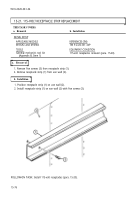
Both 115-volt receptacle wiring harnesses are removed basically
the same. This procedure covers one harness.
a. Removal
1.
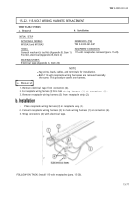
Remove electrical tape from connectors (4).
2. Cut receptacle wiring harness (3) from main
wiring harness (1) at connectors (4).
3. Remove receptacle wiring harness (3) from receptacle strip (2).
b. Installation
1.
Place receptacle wiring harness (3) in receptacle
strip (2).
2. Connect receptacle wiring harness (3) to main wiring harness (1) at connectors (4).
3. Wrap connectors (4) with electrical tape.
FOLLOW-ON TASK: Install 115-volt receptacles (para. 15-20).
15-77
Back to Top


