TM-9-2320-361-34 - Page 429 of 764
TM 9-2320-361-34
15-33.
VAN BODY
REPLACEMENT
THIS TASK COVERS:
a. Removal
b.
Installation
INITIAL SETUP
APPLICABLE MODELS
M185A3 and M109A3
TOOLS
General mechanic’s tool kit
(Appendix B, Item 1)
1-1/8-in. socket, 1/2-in. dr. (Appendix B, Item 10)
1-1/4-in. socket, 1/2-in. dr. (Appendix B, Item 19)
Lifting device
MATERIALS/PARTS
Ten locknuts (Appendix F, Item 103)
PERSONNEL REQUIRED
Two
REFERENCES (TM)
TM 9-2320-361-10
TM 9-2320-361-20
TM 9-2320-361-34P
EQUIPMENT CONDITION
●
Parking brake set (TM 9-2320-361-10).
●
Battery ground cable disconnected
(TM 9-2320-361-20).
. Front and rear splash shields removed
(TM 9-2320-361-20).
●
Ladders removed (TM 9-2320-361-20).
GENERAL SAFETY INSTRUCTIONS
●
All personnel must stand clear during lifting
operations.
●
Lifting capacity must exceed weight of van body.
a. Removal
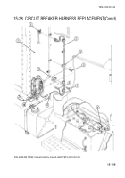
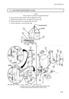
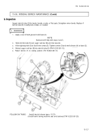
1. Disconnect lead (7) from circuit breaker (2).
2. Remove screw (5) from clamp (6).
3. Remove screw (4) from bond assembly (3).
NOTE
●
Perform step 4 if
van body
is equipped with heater.
●
Have drainage
container
ready
to
catch
fuel.
4. Loosen nut (9) and disconnect
fuel line
(8)
from elbow (1). Allow excess fuel to drain into container.
5. Remove six locknuts (18) and screws (17) from six mounting brackets (16). Discard locknuts (18).
NOTE
Step
6
applies to M109A3 vehicles.
6. Remove four locknuts (10), screws (15), washers (14), and springs (13) and (12) from two mounting
brackets (11). Discard locknuts (10).
NOTE
Step
7
applies to M185A3 vehicles.
7. Remove four locknuts (19), screws (21), eight spring keepers (20), four springs (22), and springs (23)
from two mounting brackets (11). Discard locknuts (19).
15-118
Back to Top


