TM-9-2320-361-34 - Page 609 of 764
TM 9-2320-361-34
16-10.
CONTROL VALVE REPLACEMENT (M342A2)
THIS TASK COVERS:
a.
Removal
b.
Installation
INITIAL SETUP
APPLICABLE MODELS
REFERENCES
(TM)
M342A2
TM 9-2320-361-34P
TOOLS
EQUIPMENT CONDITION
General mechanic’s tool kit
(Appendix B, Item 1)
●
Hydraulic pump removed (para. 16-12).
●
Control box removed (para. 16-11).
MATERIALS/PARTS
GENERAL SAFETY INSTRUCTIONS
Fifteen lockwashers (Appendix F, Item 125)
●
Wear eye protection when working with hydraulic
Two gaskets (Appendix F, Item 73)
hoses.
Gasket (Appendix F, Item 74)
●
Wear eye protection when removing plugs.
WARNING
Wear eye protection when working with hydraulic hoses. Fluid in
hoses may be under pressure. Failure to wear eye protection may
result in injury to personnel.
CAUTION
Cap or plug all openings immediately after disconnecting lines and
hoses to prevent contamination. Remove caps or plugs prior to
installation. Failure to do so may result in damage to equipment.
a. Removal
NOTE
●
Tag hydraulic lines for installation.
●
Have drainage container ready to catch hydraulic fluid.
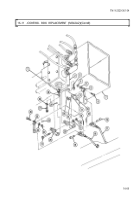
1. Disconnect six hydraulic lines (5) from two manifolds (4).
2.
Remove seven screws (6), lockwashers (7), cover (8), gasket (10), valve (3), and gasket (2) from
hydraulic tank (9). Discard lockwashers (7) and gaskets (2) and (10).
3. Remove eight screws (1), lockwashers (13), adapter (12), and gasket (11) from valve (3). Discard
lockwashers (13) and gasket (11).
4. Remove two manifolds (4) from valve (3).
b. Installation
WARNING
Wear eye protection when removing plugs. Plugs are under spring
tension and may spring out during removal. Failure to wear eye
protection may result in injury to personnel.
1. Install two manifolds (4) on valve (3).
2. Install new gasket (11) and adapter (12) on valve (3) with eight new lockwashers (13) and screws (1).
3. Install new gasket (2) and valve (3) on hydraulic tank (9) with new gasket (10), cover (8), and seven
new lockwashers (7) and screws (6).
4. Connect
six hydraulic lines (5) on two manifolds (4).
16-66
Back to Top


