TM-9-2320-361-34 - Page 611 of 764
TM 9-2320-361-34
16-11. CONTROL BOX REPLACEMENT (M342A2)
THIS TASK COVERS:
a.
Removal
b.
Installation
INITIAL SETUP
APPLICABLE MODELS
REFERENCES
(TM)
M342A2
TM 9-2320-361-10
TOOLS
TM 9-2320-361-34P
General mechanic’s tool kit
EQUIPMENT CONDITION
(Appendix B, Item 1)
Parking brake set (TM 9-2320-361-10).
MATERIALS/PARTS
Two
cotter pins (Appendix F, Item 6)
Two lockwashers (Appendix F, Item 125)
Two lockwashers (Appendix F, Item 131)
Four woodruff keys (Appendix F, Item 294)
Two screw-assembled lockwashers
(Appendix F, Item 159)
a. Removal
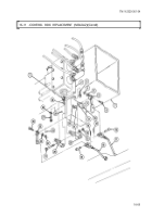
1. Remove cotter pin (12), pin (16), and control rod (17) from control rod lever (6). Discard cotter
pin (12).
2. Remove cotter pin (13), pin (19), and control rod (18) from power takeoff lever (25). Discard cotter
pin (13).
3. Remove nut (14), lockwasher (15), screw (21), two lever halves (20), and woodruff keys (29) from
camshaft (31) and valve block (1). Discard lockwasher (15) and woodruff keys (29).
4. Remove two screw-assembled lockwashers (3), screw (27), lockwasher (28), and control box (30) from
control valve (2) and hydraulic reservoir (7). Discard screw-assembled lockwashers (3) and
lockwasher (28).
5. Remove nut(4), lockwasher (5), screw (8), control rod lever (6), and woodruff key (11) from shaft (9).
Discard lockwasher (5) and woodruff key (11).
6. Remove nut (22), lockwasher (23), screw (26), power takeoff lever (25) and woodruff key (24) from
shaft (10). Discard lockwasher (23) and woodruff key (24).
b. Installation
1.
2.
3.
4.
5.
6.
Install new woodruff key (24) and power takeoff lever (25) on shaft (10) with screw (26), new lock-
washer (23), and nut (22).
Install new woodruff key (11) and control rod lever (6) on shaft (9) with screw (8), new lock-
washer (5), and nut (4).
Install control box (30) on hydraulic reservoir (7) and control valve (2) with two new screw-
assembled lockwashers (3), new lockwasher (28), and screw (27).
Install two new woodruff keys (29) and control lever halves (20) on valve block (1) and camshaft (31)
with screw (21), new lockwasher (15), and nut (14).
Install control rod (18) on power takeoff lever (25) with pin (19) and new cotter pin (13).
Install control rod (17) on control rod lever (6) with pin (19) and new cotter pin (12).
16-68
Back to Top


