TM-9-2320-361-34 - Page 617 of 764
TM 9-2320-361-34
16-14. DUMP BODY SUBFRAME MAINTENANCE
THIS TASK COVERS:
a. Removal
c. Installation
b.
Inspection
INITIAL SETUP
APPLICABLE MODELS
REFERENCES
(TM)
M342A2
TM 9-2320-361-10
TOOLS
TM 9-2320-361-20
TM 9-2320-361-34P
1-1/8-in, socket, 3/4-in. dr. (Appendix B, Item 33)
1-1/4-in. socket, 3/4-in. dr. (Appendix B, Item 37)
EQUIPMENT CONDITION
Torque wrench, 3/4-in. dr. (Appendix B, Item 6)
●
Parking brake set (TM 9-2320-361-10).
Handle, socket wrench, 3/4-in. dr.
. Hydraulic pump propeller shaft removed
(Appendix B, Item 35)
(TM 9-2320-361-20).
Lifting device
●
Splash guards removed (TM 9-2320-361-20).
Sling
●
Dump body removed (para. 15-3).
MATERIALS/PARTS
Six locknuts (Appendix
F,
Item 105)
Four locknuts (Appendix F, Item 107)
PERSONNEL REQUIRED
Two
GENERAL SAFETY INSTRUCTIONS
All personnel must stand clear during lifting
operations.
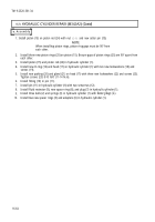
a. Removal
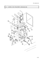
1. Remove six locknuts (5) and screws (7) from two subframe brackets (4) and frame (6). Discard
2.
3.
4.
locknuts (5).
Remove four locknuts (11), washers (12), screws (9), eight keepers (13) and, springs (14), and eight
keepers (13) from two subframe brackets (1) and frame brackets (8). Discard locknuts (11).
Attach two chains to subframe channels (2). Attach lifting device to center two chains and remove
slack from chains.
Attach two guide lines to front and rear of subframe (3).
5.
6.
7.
8,
9.
10.
11.
WARNING
All personnel must stand clear during lifting operations. A swinging
or shifting load may cause injury to personnel.
NOTE
Assistant will help guide subframe during lifting operations.
Lift subframe (3) clear of frame sill (10) and frame (6) and place on wooden supports.
Disconnect lifting device tlom two chains.
Remove two chains from subframe channels (2).
Disconnect two guide lines from front and rear of subframe (3).
NOTE
Perform steps 9 through 11 if replacing subframe with new subframe.
Remove control valve (para. 16-10).
Remove hydraulic cylinders (para. 16-8).
Remove hydraulic safety latch (para. 16-13).
16-74
Back to Top


