TM-9-2320-361-34 - Page 623 of 764
TM 9-2320-361-34
16-16. POWER DIVIDER REPAIR (M764)
THIS TASK COVERS:
a. Disassembly
c.
Assembly
b.
Cleaning and Inspection
INITIAL SETUP
APPLICABLE MODELS
M764
TOOLS
General mechanic’s tool kit
(Appendix B, Item 1)
Mechanical puller kit (Appendix B, Item 22)
Inside micrometer (Appendix B, Item 16)
Outside micrometer (Appendix B, Item 17)
Dial indicator (Appendix B, Item 21)
MATERIALS/PARTS
Three cotter pins (Appendix F, Item 20)
Cotter pin (Appendix F, Item 19)
Twenty-five lockwashers
(Appendix F, Item 125)
Four lockwashers (Appendix F, Item 131)
MATERIALS/PARTS (CONTD)
Lockwasher (Appendix F, Item 140)
Packing (Appendix F, Item 184)
Packing (Appendix F, Item 183)
Three shim sets (Appendix F, Item 260)
Three seals (Appendix F, Item 232)
Gasket (Appendix F, Item 76)
Woodruff key (Appendix F, Item 295)
Woodruff key (Appendix F, Item 292)
REFERENCES (TM)
TM 9-214
TM 9-2320-361-34P
EQUIPMENT CONDITION
Power divider removed (para. 16-15).
a. Disassembly
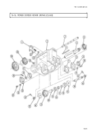
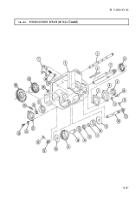
1. Remove breather (1) and bushings (2) and (3) from housing (4).
2.
3.
4.
5.
6.
7.
8.
9.
10.
11.
12.
13.
16-80
Remove three plugs
(48)
from housing (4) and cover (50).
Remove cotter pin (26), nut (27), washer (25), sprocket (24), and woodruff key (33) from shoulder
shaft (34). Discard cotter pin (26) and woodruff key (33).
Remove eight screws (5), lockwashers (6), cover (50), gasket (7), and two pins (49) from housing (4).
Discard lockwashers (6) and gasket (7).
Place shifter fork (45) in third notch of straight rod (10).
NOTE
Measure thickness of shim(s) for assembly.
Remove four screws (47), lockwashers (46), cap (43), shim(s) (44), output shaft (41), and gear (35)
from input shaft (20) and housing (4). Discard lockwashers (46) and shim(s) (44).
Remove bushing (40), bearing (39), spacers (38) and (37), and bearing (36) from output shaft (41).
Remove seal (42) from cap (43). Discard seal (42).
NOTE
Measure thickness of shim(s) for assembly.
Remove four screws (29), lockwashers (30), cap (31), and shim(s) (32) from housing (4). Discard
lockwashers (30) and shim(s) (32).
Remove seal (28) from cap (31). Discard seal (28).
Remove bushing (22) and input shaft (20) from housing (4).
Remove spacer (23) and bearing (21) from input shaft (20).
NOTE
Scribe positions of jamnuts on shifter rod and eyebolt for assembly.
Loosen jamnuts (8) and (16) on shifter rod (18) and eyebolt (17).
Back to Top


