TM-9-2320-361-34 - Page 621 of 764
TM 9-2320-361-34
16-15. POWER DIVIDER REPLACEMENT (M764)
THIS TASK COVERS:
a.
Removal
b. Installation
INITIAL SETUP
APPLICABLE MODELS
REFERENCES (TM)
M764
LO 9-2320-209-12-1
TOOLS
General mechanic’s tool kit (Appendix B, Item 1)
1-1/8-in. socket, 1/2-in. dr. (Appendix B, Item 10)
1-3/4-in. socket, 1-in. dr. (Appendix B, Item 42)
Handle, socket wrench, 1-in. dr.
(Appendix B, Item 43)
Transmission and differential lift
MATERIALS/PARTS
Two
cotter pins (Appendix F, Item 19)
Cotter pin (Appendix F, Item 10)
Four lockwashers (Appendix F, Item 140)
PERSONNEL REQUIRED
Tw o
TM 9-214
TM 9-2320-361-20
TM 9-2320-361-34P
EQUIPMENT CONDITION
.
Power divider drained (LO 9-2320-209-12-1).
●
Power
divider
propeller
shaft
removed
(TM 9-2320-361-20).
●
Earth boring machine propeller shaft
removed
(TM 9-2320-361-20).
. Air-hydraulic cylinder removed (TM 9-2320-361-20).
. Power divider drivebelt removed (para. 16-18).
GENERAL SAFETY INSTRUCTIONS
Support power divider during removal and
installation.
WARNING
Power divider is heavy. Support power divider during removal and
installation. Failure to do so may result in injury to personnel.
a. Removal
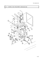
1. Remove cotter pin (2), clevis pin (1), and control rod (18) from lever (17). Discard cotter pin (2).
NOTE
Assistant will help with step 2.
2. Remove four screws (11), lockwashers (10), and power divider (4) from two brackets (3). Discard
lockwashers (10).
3. Remove cotter pin (13), nut (14), washer (15), and seal (12) from input shaft (16). Discard cotter
pin (12).
4. Remove cotter pin (7), nut (6), washer (8), and seal (9) from output shaft (5). Discard cotter pin (7).
b. Installation
1. Install seal (9) on output shaft (5) with washer (8), nut (6), and new cotter pin (7).
2. Install seal (12) on input shaft (16) with washer (15), nut (14), and new cotter pin (13).
NOTE
Assistant will help with step 3.
3. Install power divider (4) on two brackets (3) with four new lockwashers (10) and screws (11).
4. Install control rod (18) on lever (17) with clevis pin (1) and new cotter pin (2).
16-78
Back to Top


