TM-9-2330-202-13-P - Page 344 of 552
REMOVAL - Continued
6.
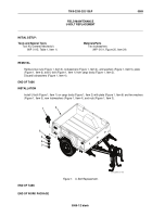
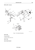
Remove two nuts (Figure 2, Item 19), cap screws (Figure 2, Item 17), lockwashers (Figure 2, Item 18), and
bracket (Figure 2, Item 9) from frame (Figure 2, Item 3) and bracket (Figure 2, Item 4). Discard lockwashers
(Figure 2, Item 18).
7.
Remove two nuts (Figure 2, Item 1), cap screws (Figure 2, Item 6), lockwashers (Figure 2, Item 5), and brackets
(Figure 2, Items 4 and 2) from frame (Figure 2, Item 3). Discard lockwashers (Figure 2, Item 5).
END OF TASK
INSTALLATION
1.
Install brackets (Figure 2, Items 2 and 4) on frame (Figure 2, Item 3) with two cap screws (Figure 2, Item 6),
new lockwashers (Figure 2, Item 5), and nuts (Figure 2, Item 1).
2.
Install bracket (Figure 2, Item 9) on frame (Figure 2, Item 3) and bracket (Figure 2, Item 4) with two cap screws
(Figure 2, Item 17), new lockwashers (Figure 2, Item 18), and nuts (Figure 2, Item 19).
3.
Install lubrication fitting (Figure 2, Item 14) on rear stabilizer (Figure 2, Item 13).
4.
Install spring (Figure 2, Item 11) and latch hook (Figure 2, Item 10) on rear stabilizer (Figure 2, Item 13).
5.
Install latch hook (Figure 2, Item 10) on rear stabilizer (Figure 2, Item 13) with straight pin (Figure 2, Item 15)
and new cotter pin (Figure 2, Item 12).
6.
Install rear stabilizer (Figure 2, Item 13) on bracket (Figure 2, Item 9) with shoulder bolt (Figure 2, Item 7) and
new self-locking nut (Figure 2, Item 8).
7.
Swing rear stabilizer (Figure 2, Item 13) up until latch hook (Figure 2, Item 10) hooks onto up-latch pin
(Figure 2, Item 16).
TM 9-2330-202-13&P
0073
0073-2
Back to Top


