TM-9-2330-238-14
CHASSIS, SEMITRAILER: 6-TON, 4-WHEEL M295A1; SEMITRAILER, VAN: EXPANSIBLE, 6-TON, 4-WHEEL M313; SEMITRAILER, VAN: SHOP, FOLDING SIDES, 6-TON, 4-WHEEL M447 AND M447C; SEMITRAILER, VAN: REPAIR PARTS, SHOP EQUIPMENT, 6-TON, 4-WHEEL M749; SEMITRAILER, VAN: REPAIR PARTS STORAGE, 6-TON, 4-WHEEL M750
TECHNICAL MANUAL; OPERATOR’S, ORGANIZATIONAL, DIRECT SUPPORT, AND GENERAL SUPPORT MAINTENANCE MANUAL
JULY 1992
TM-9-2330-238-14 - Page 380 of 462
TM 9-2330-238-14
5-27. SOLID SIDE ASSEMBLY MAINTENANCE (M313).
This Task Covers:
a.
Cleaning and Inspection
c.
Assembly
b.
Disassembly
Initial Setup:
Materials/Parts:
Tools/Test Equipment:
●
Dry cleaning solvent (Item 14, Appendix E)
●
General mechanic’s tool kit
●
Two cotter pins
●
Two gaskets
●
Four Iockwashers
I
a.
CLEANING AND INSPECTiON
I
1.
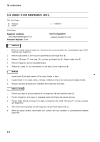
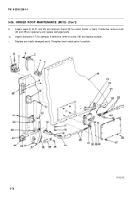
Expand side wall of van body, but do not lower hinged floor or raise hinged roof (para 2-13).
2.
Clean side wall (1) of van body with steam or water.
3.
Inspect seals (4, 9, and 12), strap (8), and angle bracket (2) around edge of side wall for cracks, breaks, or tears.
if defective, remove screws (10) and nuts (7) or rivets (3) as required, and replace defective parts.
4.
Inspect eight hook assemblies (6) for cracks, bends, or breaks. If defective, remove two bolts (5) and replace
hook assemblies.
5.
Inspect four sash assemblies for ease of operation or visual damage. If defective, replace sash assembly
(para 5-24).
6.
Inspect side door assembly for cracks, bends, breaks, or other damage. If defective, replace side door
assembly (para 5-17).
7.
Replace any badly damaged parts. Straighten bent metal parts if possible.
]
b. Disassembly
NOTE
Use steps 1 through 3 to remove left or right, front or rear, latch assemblies. Right front
latch assembly is shown.
1.
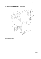
Remove eight screws (25) and access cover (24) from inside of side wall (1).
2.
Remove two cotter pins (23) and straight headed pins (22) from two locking bar rod end clevises (21). Discard
cotter pins.
3.
Remove four nuts (20), Iockwashers (19), and latch assembly (11 or 18) from sidewall (1). Discard Iockwashers.
4.
Remove two screws (13), retaining plate (14), bolt (15), and gaskets (16 and 17). Discard gaskets.
5.
Inspect latch assembly (11 or 18) for ease of operation.
I
c.
ASSEMBLY I
1.
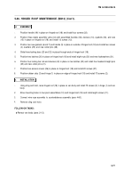
Lubricate latch assembly in accordance with Lubrication Instructions (Chapter 3, Section l).
2.
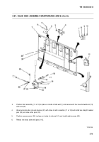
Position two new gaskets (16 and 17), bolt (15), and retaining plate (14) in place on exterior of sidewall (1) over
latch hole and secure with two screws (13).
5-78
Back to Top

