TM-9-2330-247-14-P - Page 153 of 320
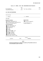
Section IX. WHEEL, HUB, AND BRAKEDRUM
Page
Hub and Brakedrum . . . . . . . . . . . . . . . . .
4-99
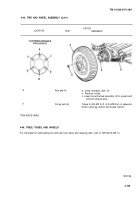
Tires, Tubes, and
Tire and Wheel Assembly . . . . . . . . . . . . . .
4-103
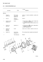
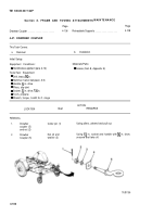
4-44. HUB AND BRAKEDRUM
TM 9-2330-247-14&P
MAINTENANC E
Page
Wheels . . . . . . . . . . . . . .
4-105
This Task Covers:
a.
Removal
b.
Installation
Initial Setup:
Equipment Conditions:
Materials/Parts:
Q Handbrakes released (para 2-10).
l Grease (Item 8, Appendix E)
. Tire and wheel assembly removed (para 4-45).
l Pressure tank drained (para 3-9).
Personnel Required:
Two
Tools/Test Equipment:
l Hammer, hand, ball-peen, 3 lb
s Handle, ratchet, X in. drive
l Puller/installer, cup
l Puller, seal
l Punch, ~z in.
l Punch, drivepin, % in. x 10 in.
l Screwdriver, cross-tip, no. 2
. Socket, z in. drive, ‘A6 in.
l Socket,
z in. drive, 1X6 in.
l Wrench, hub nut, with handle
l Wrench, torque, 0–200 Ib.-ft. range
ACTION
LOCATION
ITEM
REMARKS
NOTE
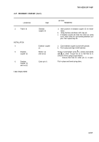
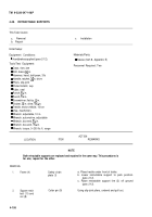
Both hubs and brakedrums are replaced In the same way. This procedure covers one
hub and brakedrum; repeat for the other.
4-99
Back to Top

