TM-9-2330-247-14-P - Page 160 of 320
TM 9-2330-247-14&P
Section X. FRAME AND TOWING ATTACHMENTS
Page
MAINTENANC E
Page
Drawbar Coupler . . . . . . . . . . . . . . . . . . . . .
4-106
Retractable Supports . . . . . . . . . . . . . . . . .
4-108
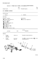
4-47. DRAWBAR COUPLER
This Task Covers:
a.
Removal
b.
Installation
Initial Setup:
Equipment Conditions:
Materials/Parts:
l Handbrakes applied (para 2-12)
l Grease (Item 8, Appendix E)
Tools/Test Equipment
l Drift, brass, % in.
l Hammer, hand, ball-peen, 3 lb
l Handle, % in. drive
l Pliers, slip-joint
l Socket, % in. drive, l% in.
l Torch, propane
l Wrench, torque, 0–600 Ib.-ft. range
ACTION
LOCATION
ITEM
REMARKS
REMOVAL
1.
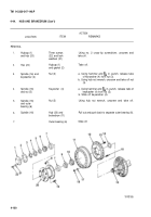
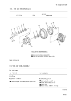
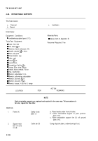
Drawbar
Cotter pin (1)
Using pliers, unbend and pull out.
coupler (5)
and nut (2)
2.
Drawbar
Nut (2) and
Using 1X in. socket and handle with % in. drive,
Coupler (5)
washer (3)
unscrew and take off.
TA701109
4-106
Back to Top

