TM-9-2330-247-14-P - Page 166 of 320
TM 9-2330-247-14&P
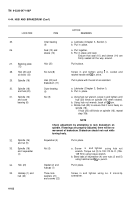
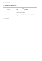
4-48.
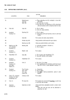
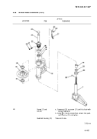
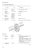
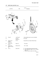
RETRACTABLE SUPPORTS (Con’t)
ACTION
LOCATION
ITEM
REMARKS
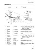
16.
17.
18.
19.
20.
21,
22.
23.
24.
25.
26.
27.
28.
29.
30.
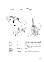
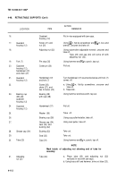
Quadrant
housing (12)
Fork (7)
Quadrant
housing (12),
handwheel (37),
and chain (27)
Quadrant
housing (12)
Bearing cup
(28) and
quadrant
housing (12)
Quadrant
housing (12)
Grease cap (34)
Tube (23)
31.
Adjusting
nut (22)
Quadrant
housing (12)
Screw (21) and
nut (20)
Adjusting nut (22)
Pin stop (35)
Cotter pin (30)
Handwheel (37)
and fork (7)
Screw (26),
chain (27), and
two S-hooks (25)
Bearing (29)
with seal (38)
Handwheel (37)
Washer (36)
Bearing cup (28)
Grease cap (34),
seal (33), and
bushing (32)
Bushing (32)
Seal (33)
Cap (24)
Mark inside
assembly.
Tube (23)
Put in vise equipped with jaw caps.
Using
~ in. flat-tip screwdriver and X6 in. box-end
wrench, unscrew and take off.
Using automotive adjustable wrench, unscrew and
take off.
Tube (23) and cap (24) will come off with
adjusting nut (22).
Using hammer and %e in. punch, tap out.
Pull out.
Turn handwheel (37) counterclockwise until fork (7)
comes off.
a. Using M in. flat-tip screwdriver, unscrew and
take off.
b. Separate.
Using hammer and brass drift, tap out.
Pull off.
Take off.
Using cup puller/installer, take off.
Using seal puller, take off.
Take out.
Take out.
Using hammer and X6 in. punch, tap off.
NOTE
of adjusting nut showing end of tube for
a. Place tube (23) and adjusting nut (22)
vertically in vise with jaw caps.
b. Using brass drift and hammer, drive out tube (23).
4-112
Back to Top

