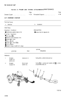
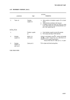
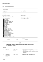
TM-9-2330-247-14-P - Page 170 of 320
TM 9-2330-247-14&P
4-48.
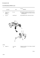
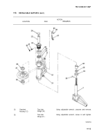
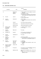
RETRACTABLE SUPPORTS (Con’t)
ACTION
LOCATION
ITEM
REMARKS
51.
52.
53.
54.
55.
56.
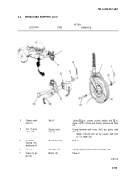
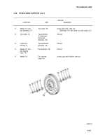
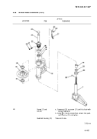
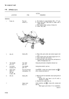
Wheel (10)
Wheel (10)
two bearing
cups (19)
Two bushings (17)
Wheel (10)
and two
bearings (18)
Wheel (10) and
two bushings (17)
Wheel (10)
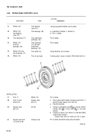
INSTALLATION
57.
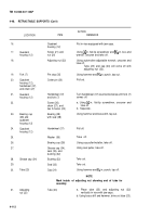
Fork (7)
58.
Fork (7) and
wheel (10)
59.
Square neck
bolt (11)
Two bearing
cups (19)
Two bearings (18)
Two preformed
packings (16)
Two bushings
(17) and two
preformed
packings (16)
Two seals (15)
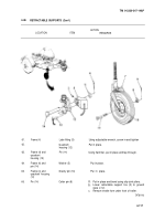
Tire (2) and tube
Using cup puller/installer, put in place,
a. Lubricate (Chapter 3, Section l).
b. Put in place.
Put in place.
Put in place.
Using hammer, put in place.
If dismounted, mount to wheel (TM 9-2610-200-14).
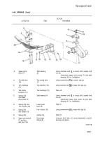
Wheel (10)
Put
Square neck
a.
bolt (11)
b.
Nut (8)
a.
60.
Square neck bolt
Cotter pin (9)
(11) and nut (8)
b.
Put
in place.
Put in place with threads of square neck bolt (11)
going through square fork hole first.
Tap with hammer.
Screw in and tighten using lZG in. socket, ratchet
handle with X in. drive, and ~~~ in. box-end
wrench.
Torque nut (8) to 140-150 Ib.-ft. (190-203 NŽm)
using torque wrench.
Ensure that hole for cotter pin (9) is open.
in place and bend using slip-joint pliers.
TA701115
4-116
Back to Top

