TM-9-2330-247-14-P - Page 162 of 320
TM 9-2330-247-14&P
4-48.
RETRACTABLE SUPPORTS
This Task Covers:
a.
Removal
c.
Installation
b. Repair
Initial Setup:
Equipment Conditions:
Materials/Parts:
l Handbrakes applied (para 2-12).
l Grease (Item 8,
Tools/Test Equipment:
l Caps, vise, jaw
l Drift, brass,
~ in.
l Hammer, hand, ball-peen, 3 lb
l Handle, ratchet, ~ in. drive
l Pliers, slip-joint
l Puller/instalilr, cup
l Puller, seal
l Punch, X6 in.
l Punch, %6 in.
l Screwdriver, flat-tip, ~ in.
l Socket, ~ in. drive, 1~6 in.
s Trestle, motor vehicle, 10 ton
s Vise, machinist’s
l Wrench, adjustable, 10 in.
l Wrench, automotive, adjustable
l Wrench, box-end, %6 in.
l Wrench, box-end, lfi6 in.
l Wrench, torque, 0–200 Ib.-ft. range
Appendix E)
Personnel Required: Two
ACTION
LOCATION
ITEM
REMARKS
NOTE
Both retractable supports are replaced and repaired in the same way. This procedures is
for one; repeat for the other.
REMOVAL
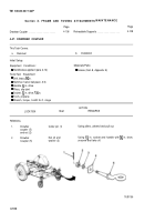
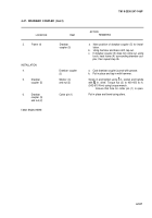
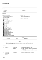
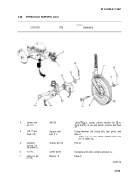
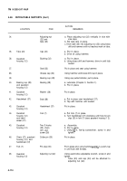
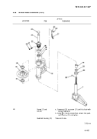
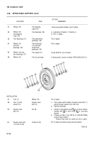
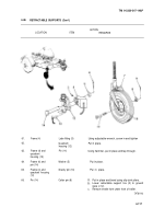
1.
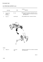
Frame (4)
2.
Square neck
bolt (11) and
nut (8)
Safety chain
plate (1)
Cotter pin (9)
a. Place trestle under front of trailer.
b. Lower retractable support to park position
(para 2-12).
c. Raise retractable support tire (2) off ground
(para 2-12).
Using slip-joint pliers, unbend and pull out.
4-108
Back to Top

