TM-9-2330-335-14-P - Page 330 of 640
TM 9-2330-335-14&P
0070-2
0070
REMOVAL
00070
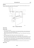
Remove stowage box (Figure 1, Item 4) from semitrailer frame (WP 0057). Grind off old welds and prepare surface for
welding of side panel brackets (Figure 1, Item 5) to frame and rail.
Figure 1.
Stowage Box Side Panel.
070
END OF TASK
INSTALLATION
00070
1.
Ensure all bare metal is painted.
2.
Insert bolt (Figure 1, Item 1) with washer (Figure 1, Item 2) through side panel (Figure 1, Item 5) mounting hole and
stowage box (Figure 1, Item 4). Place another washer on bolt inside stowage box and tighten bolt down with locknut
(Figure 1, Item 3); repeat for other three mounting locations.
3.
Position side panel brackets (Figure 1, Item 5), with stowage box (Figure 1, Item 4) installed, in place at frame (beam)
and rail.
4.
Tack weld both side panel brackets (Figure 1, Item 5) in place at frame (beam) and rail.
5.
Remove locknuts (Figure 1, Item 3), washers (Figure 1, Item 2), bolts (Figure 1, Item 1), and stowage box
(Figure 1, Item 4), leaving side panels (Figure 1, Item 5) tack-welded in place at frame (beam) and rail. Discard locknuts.
6.
Use a continuous weld on each side panel bracket (Figure 1, Item 5) to weld brackets solidly to frame (beam) and rail.
7.
Insert bolt (Figure 1, Item 1) with washer (Figure 1, Item 2) through side panel (Figure 1, Item 5) mounting hole and
stowage box (Figure 1, Item 4). Place another washer on bolt inside stowage box and tighten bolt down with new locknut
(Figure 1, Item 3); repeat for other three mounting locations.
8.
Lubricate padlocks and hinges to ensure smooth, rust-free operation. Periodically lubricate padlocks and hinges to
maintain serviceability.
END OF TASK
447-0026
Back to Top


