TM-9-2330-335-14-P - Page 348 of 640
TM 9-2330-335-14&P
0074-2
0074
INSTALLATION
00074
WARNING
•
Wear welding mask, gloves, and apron when welding or using cutting torch. Failure to wear
adequate protective clothing may result in injury to personnel.
•
Eye protection is required. Particles from grinding operations are hazardous to the eyes.
1.
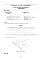
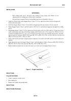
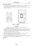
Grind area of bolster plate under kingpin (Figure 2, Item 1) 5-1/2-in.-square base flush so that new kingpin will
lie flat on the bolster plate.
2.
Install new kingpin (Figure 2, Item 1). Locate holes in kingpin top in the same manner as the one removed.
3.
Preheat kingpin (Figure 2, Item 1) and bolster plate to 150°F (66°C), and maintain temperature throughout the welding
process.
4.
Weld kingpin (Figure 2, Item 1) 5-1/2-in.-square base to bolster plate with 1/4 in. fillet weld 2 in. (51 mm) long at four
equally spaced points on the edge of the flange and plug weld the holes in the 5-1/2-in.-square base. Welds are to be in
accordance with MIL-STD-1261, class 3. Use 100,000 psi electrode or wire of the following specifications: electrodes,
mineral coated, low hydrogen, MIL-E-2200/6 type MIL-10015 or MIL-10016. Wire, use bare solid wire, low alloy steel,
MIL-E-23765/2 type 100S-1, 100S-2 or 110S-1.
5.
Inspect weld with dye penetrant or magnetic particle inspection. No cracks are allowable and any cracks found must be
repaired.
6.
Prime and paint the top of the kingpin (Figure 2, Item 1) and bolster plate as follows: Prime, per MIL-DTL-0053030 or
MIL-DTL-0053022. Paint with enamel per MIL-DTL-53039 or MIL-DTL-64159.
7.
Replace middle metal plate that was removed to gain access to the top of the kingpin (Figure 2, Item 1).
Figure 2.
Kingpin Installation.
074
END OF TASK
FOLLOW-ON TASKS
00074
1.
Connect semitrailer to prime mover.
2.
Raise landing legs.
3.
Remove/store chocks and ground boards.
END OF TASK
END OF WORK PACKAGE
447-0190
Back to Top


