TM-9-2330-342-23-P - Page 124 of 1348
CONDITION/INDICATION
Can 12 vdc cable be repaired?
DECISION
Repair - Repair 12 vdc cable (WP
0051). Go to (Step 8 - Do front side markers lights, rear side marker lights, and
rear marker lights operate?) to verify problem is solved.
No Repair - Replace 12 vdc cable. Refer to TM 9-2330-342-10 (WP
0190). Go to (Step 8 - Do front side markers
lights, rear side marker lights, and rear marker lights operate?) to verify problem is solved.
STEP 3
Are 10 to 14 vdc measured on wire 1012-2 at diode assembly connector, terminal 6?
WARNING
Remove all jewelry such as rings, ID tags, bracelets, etc. prior to working on or around vehicle.
Jewelry and tools can catch on equipment, contact positive electrical circuits, and cause a
direct short, severe burns, or electrical shock. Failure to comply may result in injury or death
to personnel.
1.
Have assistant turn OFF lights. Refer to vehicle Operator's manual (WP
0190).
2.
Have assistant turn engine start switch to OFF. Refer to vehicle Operator's manual (WP
0190).
3.
Connect 12 vdc (7 pin) cable to connector MC16.
4.
Disconnect diode assembly from diode assembly connector (WP
0059).
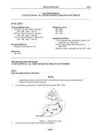
DIODE
ASSEMBLY
DIODE
ASSEMBLY
CONNECTOR
6
5
4
3
2
1
7
8
9
10
11
12
TERMINAL
6
Figure 3.
Diode Assembly Connector.
5.
Connect button probe cable red lead to diode assembly connector, terminal 6.
6.
Connect button probe cable black lead to a known good ground.
7.
Have assistant turn engine start switch to ON. Refer to vehicle Operator's manual (WP
0190).
TM 9-2330-342-23&P
0006
0006-4
Back to Top


