TM-9-2330-342-23-P - Page 566 of 1348
ALIGNMENT - Continued
8.
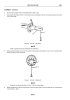
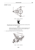
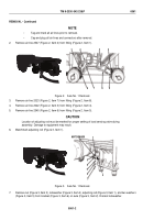
Adjust axle (Figure 5, Item 1) by moving axle forward or backwards until a 0.125 in. (3.18 mm) tolerance is
obtained.
NOTE
Replace lockwashers in sequence outlined in Steps (9) through (16) to maintain axle
alignment and to prevent axle from shifting.
9.
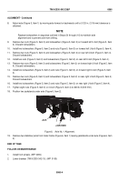
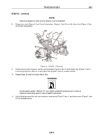
Remove two nuts (Figure 5, Item 3) and lockwashers (Figure 5, Item 2) on forward left U-bolt (Figure 5, Item
4). Discard lockwashers.
10.
Install two lockwashers (Figure 5, Item 2) and nuts (Figure 5, Item 3) on forward left U-bolt (Figure 5, Item 4).
11.
Remove two nuts (Figure 5, Item 3) and lockwashers (Figure 5, Item 2) on rear left U-bolt (Figure 5, Item 4).
Discard lockwashers.
12.
Install two nuts (Figure 5, Item 3) and lockwashers (Figure 5, Item 2) on rear left U-bolt (Figure 5, Item 4).
13.
Remove two nuts (Figure 5, Item 3) and lockwashers (Figure 5, Item 2) on forward right U-bolt (Figure 5, Item
4). Discard lockwashers.
14.
Install two lockwashers (Figure 5, Item 2) and nuts (Figure 5, Item 3) on forward right U-bolt (Figure 5, Item
4).
15.
Remove two nuts (Figure 5, Item 3) and lockwashers (Figure 5, Item 2) on rear right U-bolt (Figure 5, Item 4).
Discard lockwashers.
16.
Install two lockwashers (Figure 5, Item 2) and nuts (Figure 5, Item 3) on rear right U-bolt (Figure 5, Item 4).
17.
Tighten eight nuts (Figure 5, Item 3) on U-bolt (Figure 5, Item 4) to 600 lb-ft (813 N·m).
18.
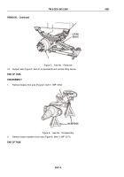
Position two jackstands under axle (Figure 6, Item 2).
JACKSTAND
JACK
1
2
Figure 6.
Axle No. 1 Alignment.
19.
Remove two stabilizer jacks from trailer frame (Figure 6, Item 1) leaving jackstands under axle (Figure 6, Item
2).
END OF TASK
FOLLOW-ON MAINTENANCE
1.
Install front wheels. (WP
0094)
2.
Lower drawbar (TM 9-2330-342-10). (WP
0190)
TM 9-2330-342-23&P
0060
0060-4
Back to Top

