TM-9-2330-342-23-P - Page 570 of 1348
REMOVAL - Continued
NOTE
•
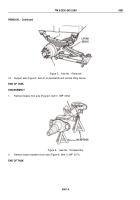
Tag and mark all air lines prior to removal.
•
Cap and plug all air lines and connectors after removal.
2.
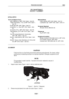
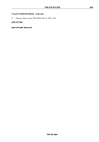
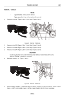
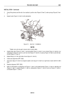
Remove air line 2547 (Figure 2, Item 2) from fitting (Figure 2, Item 1).
1
2
3
4
5
6
7
8
Figure 2.
Axle No. 1 Removal.
3.
Remove air line 2023 (Figure 2, Item 7) from fitting (Figure 2, Item 8).
4.
Remove air line 2022 (Figure 2, Item 3) from fitting (Figure 2, Item 4).
5.
Remove air line 2545 (Figure 2, Item 6) from fitting (Figure 2, Item 5).
CAUTION
Location of adjusting rod must be marked for proper setting of load sensing valve during
assembly. Damage to equipment may result.
6.
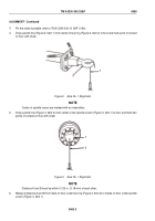
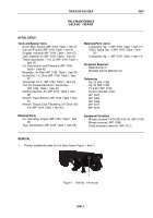
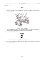
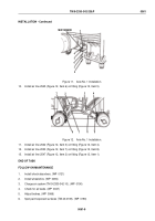
Matchmark adjusting rod (Figure 3, Item 1).
MATCHMARK
3
4
5
6
5
2
1
Figure 3.
Axle No. 1 Removal.
7.
Remove nut (Figure 3, Item 3), lockwasher (Figure 3, Item 4), adjusting rod (Figure 3, Item 1), and two washers
(Figure 3, Item 5) from bracket (Figure 3, Item 6) on axle (Figure 3, Item 2). Discard lockwasher.
TM 9-2330-342-23&P
0061
0061-2
Back to Top

