TM-9-2330-342-23-P - Page 563 of 1348
FIELD MAINTENANCE
AXLE NO. 1 ALIGNMENT
INITIAL SETUP:
Tools and Special Tools
Jack, Stabilizer (2) (WP
0194, Table 1, Item 25)
Trestle (Jackstand), 7 Ton (2) (WP
0194, Table 1,
Item 15)
Plumb Bob (WP
0194, Table 1, Item 31)
Socket Set, 1 in. Drive (WP
0194, Table 1, Item
37)
Socket Set, 3/4 in. (WP
0194, Table 1, Item 35)
Tape Measure, 25 FT (WP
0194, Table 1, Item
15)
Tool Kit, General Mechanic's: Automotive
(WP
0194, Table 1, Item 47)
Wrench, Impact Electric (WP
0194, Table 1, Item
51)
Wrench, Torque, Click, Ratcheting, 3/4" Drive, 600
ft-lb (WP
0194, Table 1, Item 42)
Materials/Parts
Chalk, Marking (WP
0193, Table 1, Item 12)
Lockwasher Qty:
8 (WP
0195, Table 1, Item 21)
Personnel Required
Wheeled Vehicle Mechanic (2)
References
Fig. 34 (WP
0169)
Equipment Condition
Wheels chocked (TM 9-2330-342-10). (WP
0190)
Front wheels removed. (WP
0094)
Drawbar level (TM 9-2330-342-10). (WP
0190)
ALIGNMENT
CAUTION
Trailer must be on a hard level surface when performing axle alignment. An uneven surface
could cause a misreading resulting in an improper alignment. Damage to equipment could
result.
NOTE
This procedure is used if axle No. 1 has been removed or replaced or as part of
troubleshooting.
1.
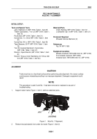
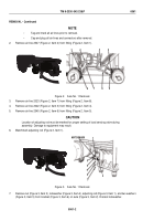
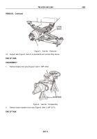
Support trailer frame (Figure 1, Item 1) with two stabilizer jacks.
JACKSTAND
JACK
1
2
Figure 1.
Axle No. 1 Alignment.
2.
Remove two jackstands from under front axle (Figure 1, Item 2).
TM 9-2330-342-23&P
0060
0060-1
Back to Top

