TM-9-2330-342-23-P - Page 571 of 1348
REMOVAL - Continued
NOTE
Note the orientation of axles prior to removal to aid in installation.
8.
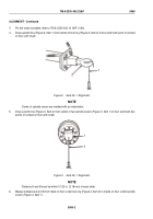
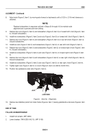
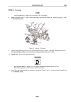
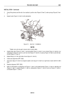
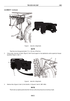
Remove four nuts (Figure 4, Item 5) and lockwashers (Figure 4, Item 4) from left side of axle (Figure 4, Item
3). Discard lockwashers.
1
2
3
4
5
6
7
Figure 4.
Axle No. 1 Removal.
9.
Remove two U-bolts (Figure 4, Item 6), spring bracket (Figure 4, Item 7), and rubber stop (Figure 4, Item 1)
from springs (Figure 4, Item 2) on left side of axle (Figure 4, Item 3). Discard U-bolts.
10.
Repeat Steps (8) and (9) for right side of axle.
WARNING
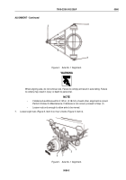
Axle assembly weighs 1,565 lbs (711 kg). Attach suitable lifting device prior to removal.
Failure to comply may result in injury or death to personnel.
11.
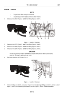
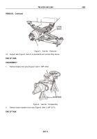
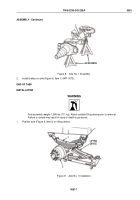
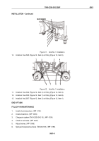
Using lifting device and the aid of an assistant, raise spring (Figure 5, Item 1) and remove axle (Figure 5, Item
2) from beneath spring.
TM 9-2330-342-23&P
0061
0061-3
Back to Top

