TM-9-2330-342-23-P - Page 576 of 1348
INSTALLATION - Continued
2.
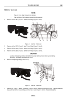
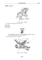
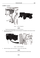
Using lifting device and the aid of an assistant, position axle (Figure 9, Item 2) under springs (Figure 9, Item
1).
3.
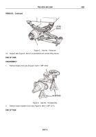
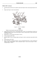
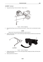
Support axle (Figure 10, Item 3) with jackstands.
1
2
3
4
5
6
7
Figure 10.
Axle No. 1 Installation.
NOTE
Tighten nuts only enough to secure axle in place safely.
4.
Install rubber stop (Figure 10, Item 1), spring bracket (Figure 10, Item 7), two U-bolts (Figure 10, Item 6), four
lockwashers (Figure 10, Item 4), and four nuts (Figure 10, Item 5) on spring (Figure 10, Item 2) and left side
of axle (Figure 10, Item 3).
5.
Repeat Step (4) for the right side of axle (Figure 10, Item 3).
6.
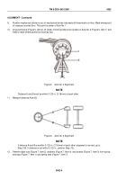
Check axle alignment (WP
0060).
7.
Once axle (Figure 10, Item 3) is aligned, tighten nuts (Figure 10, Item 5) on right side of axle to 600 lb-ft (814
N·m).
8.
Recheck alignment (WP
0060).
9.
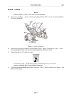
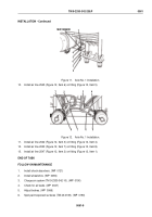
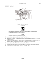
Refer to matchmarks on adjusting rod (Figure 11, Item 1) and install washer (Figure 11, Item 4), adjusting rod
(Figure 11, Item 1), washer (Figure 11, Item 4), lockwashers (Figure 11, Item 3), and nut (Figure 11, Item 2)
on bracket (Figure 11, Item 5).
TM 9-2330-342-23&P
0061
0061-8
Back to Top

