TM-9-2330-342-23-P - Page 582 of 1348
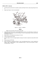
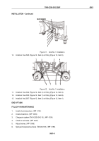
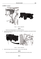
ALIGNMENT - Continued
9.
Position mechanical divider so arc of mechanical divider intersects all three marks on floor. Mark where point
of compass touches floor. This point is center of Axle No. 1.
10.
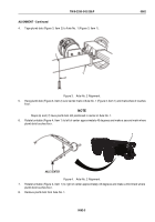
Drop plumb bob (Figure 5, Item 2) off center of both spindle cover centers of Axle No. 2 (Figure 5, Item 1) and
make a mark where plumb bob touches floor.
1
2
Figure 5.
Axle No. 2 Alignment.
NOTE
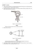
Distance A and B must be within 0.125 in. (3.18 mm) of each other.
11.
Measure distance A and B.
Figure 6.
Axle No. 2 Alignment.
NOTE
If distance A and B are within 0.125 in. (3.18 mm) of each other, alignment is correct, go to
Step (18). If distance is not within 0.125 in., perform Step (12).
12.
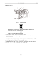
Remove eight nuts (Figure 7, Item 5), washers (Figure 7, Item 4), and screws (Figure 7, Item 3) from spring
seat cap (Figure 7, Item 1) and spring seat (Figure 7, Item 7).
TM 9-2330-342-23&P
0062
0062-4
Back to Top

