TM-9-2330-342-23-P - Page 586 of 1348
ALIGNMENT - Continued
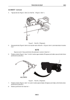
3.
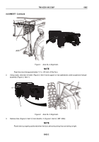
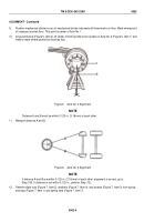
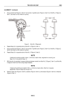
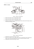
Drop a plumb bob (Figure 2, Item 3) from center of spindle cover (Figure 2, Item 4) on Axle No. 2 (Figure 2,
Item 1) and mark on floor where it touches.
4
3
1
2
Figure 2.
Axle No. 3 Alignment.
4.
Repeat Step (3) for opposite side of Axle No. 2 (Figure 2, Item 1).
5.
Drop a plumb bob (Figure 2, Item 3) from center of spindle cover (Figure 2, Item 4) on Axle No. 3 (Figure 2,
Item 2) and mark on floor where it touches.
6.
Repeat Step (5) for opposite side of Axle No. 3 (Figure 2, Item 2).
NOTE
If distance A and B are within 0.06 in. (1.52 mm) of each other, alignment is correct; go to
Step (14). If not, perform Step (7).
7.
With the aid of an assistant, measure distance between marks from Axle No. 2 (Figure 2, Item 1) and Axle No.
3 (Figure 2, Item 2) on floor using a tape measure.
NOTE
If distance A and B are not within 0.06 in. (1.52 mm) of each other, Axle No. 3 requires
adjustment. Perform Steps (8) through (14).
8.
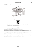
Remove eight nuts (Figure 3, Item 5), washers (Figure 3, Item 4), and screws (Figure 3, Item 3) on bracket
(Figure 3, Item 1).
TM 9-2330-342-23&P
0063
0063-2
Back to Top

