TM-9-2330-342-23-P - Page 583 of 1348
ALIGNMENT - Continued
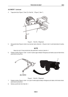
1
2
3
4
5
6
7
8
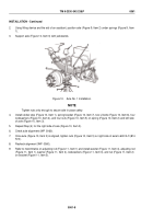
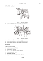
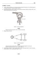
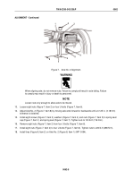
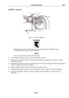
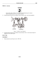
Figure 7.
Axle No. 2 Alignment.
WARNING
When aligning axle, do not remove nuts. Failure to comply will result in axle falling. Failure
to comply may result in injury or death to personnel.
NOTE
Loosen nuts only enough to allow axle to be moved.
13.
Loosen eight nuts (Figure 7, Item 2) on four U-bolts (Figure 7, Item 6).
14.
Adjust Axle No. 2 (Figure 7, Item 8) by moving axle ends forward or backwards until a 0.125 in. (3.18 mm)
tolerance is obtained.
15.
Install eight screws (Figure 7, Item 3), washers (Figure 7, Item 4), and nuts (Figure 7, Item 5) to spring seat
cap (Figure 7, Item 1) and spring seat (Figure 7, Item 7). Tighten nuts to 130 lb-ft (176 N·m).
16.
Remove eight nuts (Figure 7, Item 2) from four U-bolts (Figure 7, Item 6).
17.
Install eight nuts (Figure 7, Item 2) to four U-bolts (Figure 7, Item 6). Tighten nuts to 220 lb-ft (298 N·m).
18.
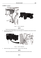
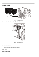
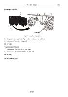
Install tires (Figure 8, Item 2) on Axle No. 2 (Figure 8, Item 1) (WP
0094).
TM 9-2330-342-23&P
0062
0062-5
Back to Top

