TM-9-2330-342-23-P - Page 628 of 1348
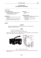
INSTALLATION - Continued
1
2
3
4
5
6
7
8
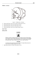
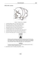
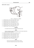
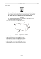
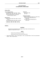
Figure 7.
Air Reservoir No. 1 Installation.
11.
Install fitting (Figure 7, Item 2) on air reservoir (Figure 7, Item 3).
12.
Apply sealing compound on threads of fitting (Figure 7, Item 1).
13.
Install fitting (Figure 7, Item 1) on fitting (Figure 7, Item 2).
14.
Apply sealing compound on threads of fitting (Figure 7, Item 5).
15.
Install fitting (Figure 7, Item 5) on air reservoir (Figure 7, Item 3).
16.
Apply sealing compound on threads of fitting (Figure 7, Item 6).
17.
Install fitting (Figure 7, Item 6) on fitting (Figure 7, Item 5).
CAUTION
Do not tighten check valve by its body. Damage to check valve may result.
NOTE
The valve is marked with an arrow indicating the direction in which it should be installed. Note
direction of arrow before installation.
18.
Apply sealing compound on threads of check valve (Figure 7, Item 8).
19.
Install check valve (Figure 7, Item 8) on fitting (Figure 7, Item 6).
20.
Apply sealing compound on threads of fitting (Figure 7, Item 7).
21.
Install fitting (Figure 7, Item 7) on check valve (Figure 7, Item 8).
22.
Apply sealing compound on threads of fitting (Figure 7, Item 4).
23.
Install fitting (Figure 7, Item 4) on fitting (Figure 7, Item 5).
NOTE
•
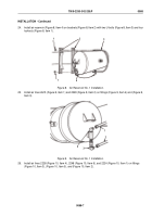
Drain valve must be at the bottom when installing air reservoir.
•
U-bolts must be installed through notches on each end of bracket.
TM 9-2330-342-23&P
0068
0068-6
Back to Top

