TM-9-2330-342-23-P - Page 634 of 1348
INSTALLATION - Continued
2
3
4
5
1
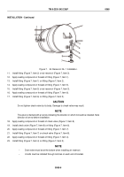
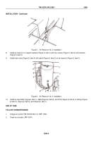
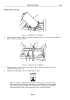
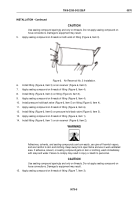
Figure 5.
Air Reservoir No. 2 Installation.
8.
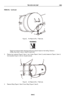
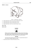
Install air reservoir on support brackets (Figure 5, Item 3) with four screws (Figure 5, Item 2) and locknuts
(Figure 5, Item 5).
9.
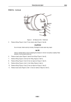
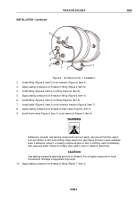
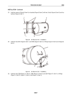
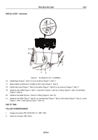
Install drain valve (Figure 6, Item 4) with cable (Figure 6, Item 5) on air reservoir (Figure 6, Item 3).
1
9
8
7
6
5
4
3
2
Figure 6.
Air Reservoir No. 2 Installation.
10.
Install air lines 2605 (Figure 6, Item 1), 2606 (Figure 6, Item 8), and 2019 (Figure 6, Item 9) on fittings (Figure
6, Item 2), (Figure 6, Item 6), and (Figure 6, Item 7).
END OF TASK
FOLLOW-ON MAINTENANCE
1.
Charge air system (TM 9-2330-342-10). (WP
0190)
2.
Check for air leaks. (WP
0047)
TM 9-2330-342-23&P
0069
0069-4
Back to Top

