TM-9-2330-342-23-P - Page 639 of 1348
REMOVAL - Continued
1
2
3
4
5
7
8
9
6
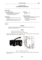
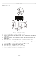
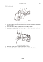
Figure 2.
Air Reservoir No. 3 Removal.
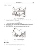
11.
Remove two locknuts (Figure 2, Item 5), screws (Figure 2, Item 4), and clamps (Figure 2, Item 3) from
crossmembers (Figure 2, Item 6). Discard locknuts.
NOTE
Electrical and air lines may need to be pulled to one side.
12.
Remove four locknuts (Figure 2, Item 8) and screws (Figure 2, Item 9) from air reservoir bracket (Figure 2,
Item 7). Discard locknuts.
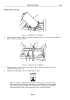
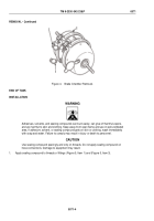
13.
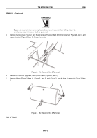
Rotate air reservoir (Figure 3, Item 2) on end and remove from trailer frame (Figure 3, Item 1).
1
2
Figure 3.
Air Reservoir No. 3 Removal.
END OF TASK
INSTALLATION
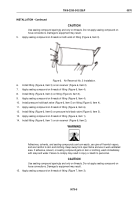
1.
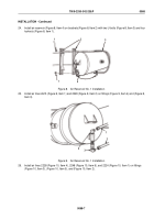
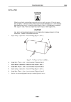
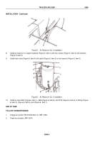
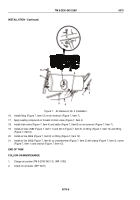
Position air reservoir (Figure 4, Item 2) in trailer frame (Figure 4, Item 1).
TM 9-2330-342-23&P
0070
0070-3
Back to Top

