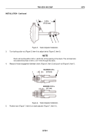
TM-9-2330-342-23-P - Page 699 of 1348
INSTALLATION - Continued
3
4
2
5
6
7
8
9
10
MATCH
MARK
1
17
16
15
14
13
12
11
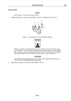
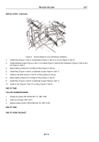
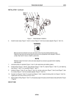
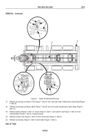
Figure 7.
Slack Adjuster Installation.
6.
Install tie down strap (Figure 7, Item 5) on boot (Figure 7, Item 6) and slack adjuster (Figure 7, Item 10).
WARNING
Wear proper eye protection and use care when removing and installing retaining rings.
Retaining rings are under spring tension and can act as projectiles when released. Failure to
comply may result in injury or death to personnel.
NOTE
Attempt to align the holes in clevis and slack adjuster as closely as possible when installing
slack adjuster.
7.
Lubricate splines of camshaft (Figure 7, Item 7) with automotive and artillery grease.
8.
Install washer (Figure 7, Item 8), slack adjuster (Figure 7, Item 10), washer (Figure 7, Item 12), and retaining
ring (Figure 7, Item 13) on camshaft (Figure 7, Item 7).
9.
Install pin (Figure 7, Item 15), pin (Figure 7, Item 14), and two cotter pins (Figure 7, Item 3) and (Figure 7, Item
4) on clevis (Figure 7, Item 2) and slack adjuster (Figure 7, Item 10).
10.
Turn jam nut (Figure 7, Item 17) on push rod (Figure 7, Item 1) against locking collar nut (Figure 7, Item 16).
Tighten jam nut to 20 to 30 lb-ft (27 to 41 N·m).
11.
Apply grease to fitting (Figure 7, Item 11) until grease purges from pressure relief seal under pawl button (Figure
7, Item 9).
END OF TASK
TM 9-2330-342-23&P
0078
0078-5
Back to Top

