TM-9-2330-342-23-P - Page 700 of 1348
ADJUSTMENT
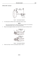
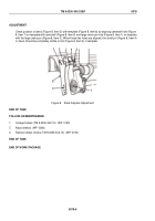
Check position of clevis (Figure 8, Item 5) with template (Figure 8, Item 8) by aligning camshaft hole (Figure
8, Item 7) on template with camshaft (Figure 8, Item 6) and large clevis pin hole (Figure 8, Item 1) on template
with the large clevis pin (Figure 8, Item 3). When these two holes are aligned, the small pin (Figure 8, Item 4)
in clevis should be completely visible in slot (Figure 8, Item 2) in template.
1
2
3
4
5
6
7
8
Figure 8.
Slack Adjuster Adjustment.
END OF TASK
FOLLOW-ON MAINTENANCE
1.
Uncage brakes (TM 9-2330-342-10). (WP
0190)
2.
Adjust brakes. (WP
0066)
3.
Remove wheel chocks (TM 9-2330-342-10). (WP
0190)
END OF TASK
END OF WORK PACKAGE
TM 9-2330-342-23&P
0078
0078-6
Back to Top


