TM-9-2330-342-23-P - Page 694 of 1348
INSTALLATION - Continued
1
2
3
4
5
5
6
7
8
9
10
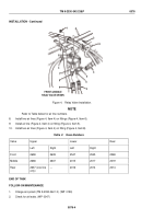
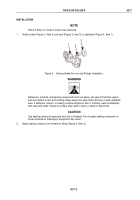
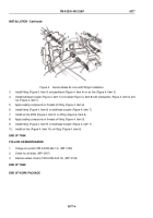
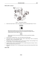
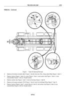
Figure 4.
Service Brake Air Line and Fittings Installation.
3.
Install fitting (Figure 4, Item 3) and gladhand (Figure 4, Item 4) on air line (Figure 4, Item 5).
4.
Install bulkhead coupler (Figure 4, Item 7) on bracket (Figure 4, Item 8) with lockwasher (Figure 4, Item 2) and
nut (Figure 4, Item 1).
5.
Apply sealing compound on threads of fitting (Figure 4, Item 6).
6.
Install fitting (Figure 4, Item 6) on bulkhead coupler (Figure 4, Item 7).
7.
Install air line 2255 (Figure 4, Item 5) on fitting (Figure 4, Item 6).
8.
Apply sealing compound on threads of fitting (Figure 4, Item 9).
9.
Install fitting (Figure 4, Item 9) on bulkhead coupler (Figure 4, Item 7).
10.
Install air line (Figure 4, Item 10) on fitting (Figure 4, Item 9).
END OF TASK
FOLLOW-ON MAINTENANCE
1.
Charge air system (TM 9-2330-342-10). (WP
0190)
2.
Check for air leaks. (WP
0047)
3.
Remove wheel chocks (TM 9-2330-342-10). (WP
0190)
END OF TASK
END OF WORK PACKAGE
TM 9-2330-342-23&P
0077
0077-4
Back to Top


