TM-9-2330-342-23-P - Page 685 of 1348
FIELD MAINTENANCE
RELAY VALVE REPLACEMENT
INITIAL SETUP:
Tools and Special Tools
Cap and Plug Set (WP
0194, Table 1, Item 4)
Tool Kit, General Mechanic's: Automotive
(WP
0194, Table 1, Item 47)
Materials/Parts
Tags, Identification (WP
0193, Table 1, Item 59)
Sealing Compound (WP
0193, Table 1, Item 55,
56, 57)
Locknut Qty:
2 (WP
0195, Table 1, Item 81)
References
Fig. 17 (WP
0152)
References (cont.)
Fig. 18 (WP
0153)
WP
0047
Equipment Condition
Wheels chocked (TM 9-2330-342-10). (WP
0190)
Air system drained (TM 9-2330-342-10).
(WP
0190)
REMOVAL
CAUTION
Equipment may be damaged by foreign matter if hoses, tubes, and connectors are not
plugged and capped when removed.
NOTE
•
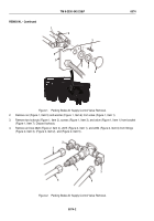
All three relay valves are removed and installed the same way. The rear relay valve
has only four airlines and a fitting attached, rather than a fitting on top of the valve,
like the front and middle valves.
•
Tag all air lines and fittings prior to removal.
•
Cap and plug all air lines and connectors after removal.
•
Refer to Table below for air line numbers.
Table
1.
Hose Numbers.
Valve
Upper
Lower
Rear
Left
Right
Left
Right
Front
2638
2639
2547
2545
2548
Middle
2638
2637
2015
2017
2019
Rear
2637 (one line
only)
---
2016
2014
2014
TM 9-2330-342-23&P
0076
0076-1
Back to Top

