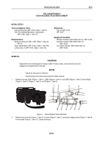
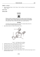
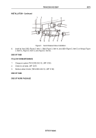
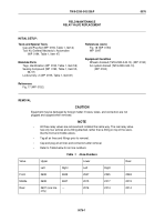
TM-9-2330-342-23-P - Page 679 of 1348
INSTALLATION - Continued
2
1
5
6
3
4
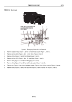
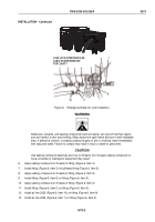
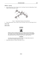
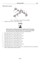
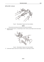
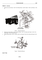
Figure 5.
Parking Brake Air Supply Control Valve Installation.
NOTE
Ensure that the screw holes are at the top of the valve during installation.
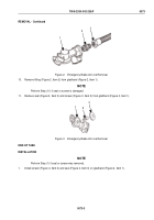
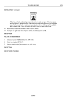
14.
Install valve (Figure 6, Item 1) on bracket (Figure 6, Item 7) with two screws (Figure 6, Item 3) and locknuts
(Figure 6, Item 2).
8
7
2
1
3
4
5
6
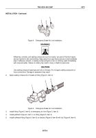
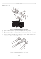
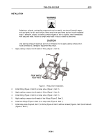
Figure 6.
Parking Brake Air Supply Control Valve Installation.
15.
Install washer (Figure 6, Item 6) and nut (Figure 6, Item 5) on shaft (Figure 6, Item 8).
TM 9-2330-342-23&P
0074
0074-5
Back to Top

