TM-9-2330-342-23-P - Page 683 of 1348
INSTALLATION - Continued
1
2
3
10
9
8
7
6
5
4
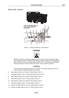
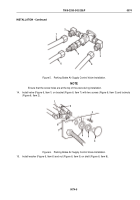
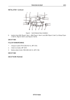
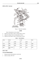
Figure 3.
Quick Release Valve Installation.
8.
Install air lines 2260 (Figure 3, Item 1), 2660 (Figure 3, Item 4), and 2639 (Figure 3, Item 5) on fittings (Figure
3, Item 9), (Figure 3, Item 3), and (Figure 3, Item 6).
END OF TASK
FOLLOW-ON MAINTENANCE
1.
Charge air system (TM 9-2330-342-10). (WP
0190)
2.
Check for air leaks. (WP
0047)
3.
Remove wheel chocks (TM 9-2330-342-10). (WP
0190)
END OF TASK
END OF WORK PACKAGE
TM 9-2330-342-23&P
0075
0075-3/4 blank
Back to Top

