TM-9-2330-342-23-P - Page 688 of 1348
INSTALLATION - Continued
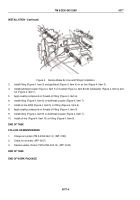
1
2
3
4
4
5
6
4
4
4
7
8
6
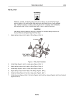
FRONT & MIDDLE
RELAY VALVE SHOWN
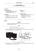
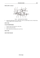
Figure 4.
Relay Valve Installation.
NOTE
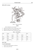
Refer to Table below for air line numbers.
8.
Install two air lines (Figure 4, Item 4) on fittings (Figure 4, Item 6).
9.
Install air line (Figure 4, Item 4) on fitting (Figure 4, Item 5).
10.
Install two air lines (Figure 4, Item 4) on fitting (Figure 4, Item 8).
Table
2.
Hose Numbers.
Valve
Upper
Lower
Rear
Left
Right
Left
Right
Front
2638
2639
2547
2545
2548
Middle
2638
2637
2015
2017
2019
Rear
2637 (one line
only)
---
2016
2014
2014
END OF TASK
FOLLOW-ON MAINTENANCE
1.
Charge air system (TM 9-2330-342-10). (WP
0190)
2.
Check for air leaks. (WP
0047)
TM 9-2330-342-23&P
0076
0076-4
Back to Top

