TM-9-2330-342-23-P - Page 698 of 1348
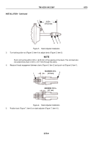
INSTALLATION - Continued
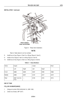
6.95 in.
(176.53 mm)
1
2
3
4
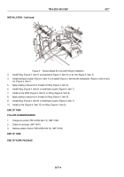
Figure 5.
Slack Adjuster Installation.
3.
Turn locking collar nut (Figure 5, Item 4) to adjust clevis (Figure 5, Item 3).
NOTE
Push rod must be within 0.25 in. (6.35 mm) of the opening in the clevis. The rod must also
not extend more than 0.125 in. (3.17 mm) through the clevis.
4.
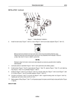
Measure thread engagement between clevis (Figure 6, Item 2) and push rod (Figure 6, Item 1).
MAXIMUM 0.25 in.
(6.35 mm)
MAXIMUM 0.125 in.
(3.17 mm)
1
2
Figure 6.
Slack Adjuster Installation.
5.
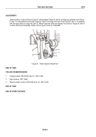
Position boot (Figure 7, Item 6) on slack adjuster (Figure 7, Item 10).
TM 9-2330-342-23&P
0078
0078-4
Back to Top

