TM-9-2350-238-20-1 - Page 522 of 1364
TM 9-2350-238-20-1
2-55. MAINTENANCE OF THROTTLE AND ACCELERATOR CONTROLS AND LINKAGE
(DRIVER’S COMPARTMENT).
This task covers:
a. Removal
b. lnspection/Repair
c.
Installation
INITIAL SETUP
Matenals/Parts
Equipment Conditions
Cotter pin
2-938 Hull transmission compartment
LockWasher (5)
deck assembly removed
LockWasher (2)
2-935 Hull engine compartment deck
Self-locking nut
assembly lid removed
References
TM 9-2350-238-24P-1
1
2
3
4
5
6
7
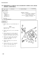
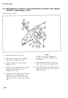
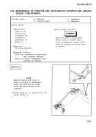
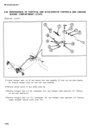
Remove cotter pin (1) and slotted plain nut
(2) .
NOTE
Use care not to lose or damage
cotter pin or pin.
Remove cotter pin (3), pin (4), and throttle
plate (5).
Remove spring pin (6), control pedal (7),
two sleeve bearings (8), and two helical
springs (9) from manual control lever (10).
Remove two hexagon head capscrews
(11) and two Iockwashers (12) from
accelerator shaft (13).
Remove self-locking nut (14) and flat
washer (15).
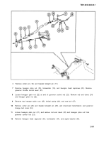
Remove machine key (16), accelerator
shaft (13), and sleeve bearing (17).
Remove manual control lever (10).
2-496
Back to Top

