TM-9-2350-238-20-1 - Page 524 of 1364
TM 9-2350-238-20-1
2-55. MAINTENANCE OF THROTTLE AND ACCELERATOR CONTROLS AND LINKAGE
(DRIVER’S COMPARTMENT) (CONT).
INSTALLATION (CONT)
4
5
6
7
8
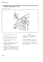
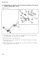
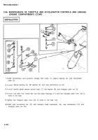
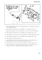
Install manual control lever (12).
Install sleeve bearing (13), accelerator
shaft (14), and machine key (15).
Install flat washer (16) and new self-
9
locking nut (17).
Install two new Iockwashers (18) and two
10
hexagon head capscrews (19) on
accelerator shaft (14).
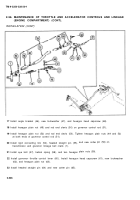
Install two helical springs (20), two sleeve
bearings (21 ), control pedal (22), and
spring pin (23) on manual control lever
(12). Allow 0.005 in. (0.013 cm) minimum
play.
NOTE
If cotter pin or pin are damaged or
missing, a new clevis assembly must
be ordered.
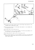
Install throttle plate (24), pin (25), and
cotter pin (26) on clevis assembly (27).
Install throttle plate (24), slotted plain nut
(28), and new cotter pin (29) on manual
control lever (12).
2-498
Back to Top

