TM-9-2350-238-20-1 - Page 535 of 1364
TM 9-2350-238-20-1
13
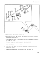
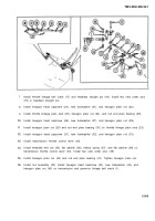
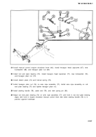
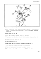
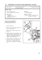
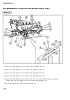
Tighten hexagon plain nuts (16).
14
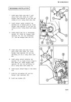
Position transmission and governor linkage bell crank (8) at right angles to throttle linkage plain
stud (17) by holding throttle linkage bell crank (15) in position and adjust
stud rod ends.
15
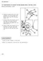
Tighten hexagon plain nuts (18).
16
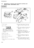
Position rigid connecting link (9) toward governor (19) (idle position).
17
18
19
20
21
22
23
throttle linkage plain
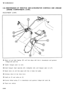
Adjust rod end clevis (20) until hole alines with hole in transmission and governor linkage bell
crank (8).
Unscrew rod end clevis (20) one more turn.
Tighten hexagon plain nut (21).
Attach rod end clevis (20) to transmission and governor linkage bell crank (8).
Install headed straight pin (6) and cotter pin (5) to rod end clevis (20).
Rotate and hold transmission throttle control lever (22) fully clockwise.
Position rigid connecting link (9) away from governor (19) (full-throttle position).
2-509
Back to Top

