TM-9-2350-238-20-1 - Page 805 of 1364
3
4
5
6
7
8
9
10
11
12
13
14
15
16
17
18
19
TM 9-2350-238-20-1
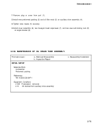
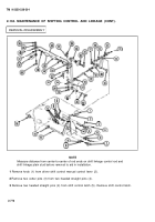
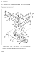
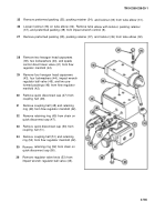
Install rod end plain bearing (5) on shift control linkage bellcrank (4). Secure to hull with new
Iockwasher (6) and machine bolt (7).
Install two hexagon plain nuts (8), and two rod end plain bearings (9 and 10) on ends of shift
linkage control rod (11).
Install hexagon head capscrew (12), flat washer (13), rigid shift linkage connecting link (14),
new Iockwasher (15), and hexagon plain nut (16) on shift linkage rod remote control lever (17).
Install hexagon head capscrew (18), new Iockwasher (19), and hexagon plain nut (20) through
shift control linkage bellcrank (4) and rod end plain bearing (9).
Tighten two hexagon plain nuts (8) at ends of shift linkage control rod (11).
Install two hexagon plain nuts (21) and two rod end plain bearings (22) on shift linkage plain
stud (23).
Install hexagon head capscrew (24), new Iockwasher (25), and hexagon plain nut (26) through
rod end plain bearing (22) and shift control linkage bellcrank (4).
Tighten two hexagon plain nuts (21) at ends of shift linkage plain stud (23).
Install linkage shift control shift arm lever (27). Install hexagon head capscrew (28), new lock-
washer (29), and hexagon plain
control shift arm lever.
Install two sleeve bearings (31),
nut (30) through rod end plain bearing (22) and linkage shift
woodruff
(33) .
Install hexagon head capscrew (34), new
linkage shift control shift arm lever (27).
Install access cover (37) on bulkhead.
key (32), and driver shift control manual control lever
Iockwasher (35), and hexagon plain nut (36) through
Install eight flat washers (38), two new Iockwashers (39), and two hexagon head capscrews
(40) through access cover (37).
Install helical spring (41 ) on driver shift control manual control lever (33).
Install shift control latch (42). Install two headed straight pins (43)
Install two new cotter pins (44) in two headed straight pins (43).
Install knob (45) on driver shift control manual control lever (33).
in shift control latch.
2-779
Back to Top

