TM-9-2350-238-20-1 - Page 847 of 1364
TM 9-2350-238-20-1
1
2
3
4
5
6
7
8
9
10
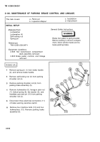
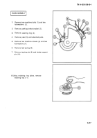
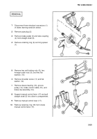
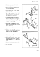
Disconnect three electrical connectors (1)
of brake warning sensitive switch.
Remove pipe plug (2).
Remove brake pedal (3) and tube coupling
(4) from straight shaft (5).
Remove retaining ring (6) and ring spacer
(7) .
Remove two self-locking nuts (8), two
hexagon plain nuts (9), and two flat
washers (10).
Remove shoulder screw (11) and flat
washer (12).
Remove sleeve bearing (13), groove
pulley (14), brake control cable (15), and
brake clip assembly (16).
Support manual control lever (17) and pull
straight shaft (5) into driver’s compartment.
Remove manual control lever (17).
Remove retaining ring (18) from inside
manual control lever (17).
2-821
Back to Top

