TM-9-2350-238-20-1 - Page 840 of 1364
TM 9-2350-238-20-1
2-140. MAINTENANCE OF PARKING BRAKE CONTROL AND LINKAGE.
This task covers:
a.
Removal
c.
Installation
b.
lnspection/Repair
d.
Adjustment
INITIAL SETUP
Materials/Parts
General Safety Instructions
Lockwasher
Lockwasher (4)
Self-locking nut
Spring pin
Brake foot pedal is spring-loaded.
Before working in driver's compart-
References
ment, block vehicle tracks and re-
TM 9-2350-238-24P-1
lease parking brake.
Equipment Conditions
2-938 Hull transmission compartment
deck assembly removed
2-820 Brake pedal, controls, and linkage
removed
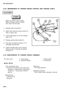
REMOVA L
1
2
3
4
5
6
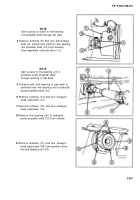
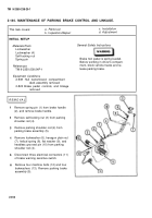
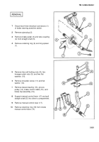
Remove spring pin (1) from brake handle
(2), and remove brake handle.
Remove self-locking nut (3) from parking
shoulder rod (4).
Remove parking shoulder rod (4) from
parking brake assembly (5).
Remove Iockwasher (6), hexagon plain nut
(7), helical spring (8), flat washer (9), and
headless grooved pin (10) from parking
shoulder rod (4).
Disconnect three electrical connectors (11)
of brake warning sensitive switch.
Remove four machine bolts (12) and four
Iockwashers (13). Remove parking brake
assembly (5).
2-814
Back to Top

