TM-9-2350-238-20-1 - Page 835 of 1364
TM 9-2350-238-20-1
NOTE
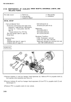
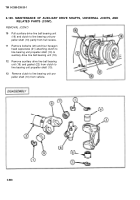
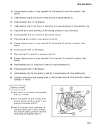
Disassembly steps are written for one universal joint but apply to all six universal
joints.
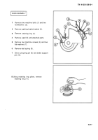
1
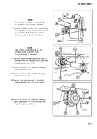
Remove four retaining rings (1).
2
Support propeller shaft (2) with wood block placed under propeller shaft close to universal joint.
3
Rotate propeller shaft (2) so yoke (3) is positioned with bearing (4) facing up.
4
Tap yoke (3) with soft-faced hammer forcing bearing (4) from yoke. Remove bearing.
5
Rotate propeller shaft (2) 180 degrees so yoke (3) is positioned with bearing (5) facing up.
6
Tap yoke (3) with soft-faced hammer forcing bearing (5) from yoke. Remove bearing.
7
Remove yoke (3) from cross assembly (6).
8
Rotate and position propeller shaft (2) with bearing (7) in shaft yoke (8) facing up. Remove
bearing.
9
Rotate shaft yoke (8) 180 degrees and remove bearing (7).
10
Remove cross assembly (6) from shaft yoke (8).
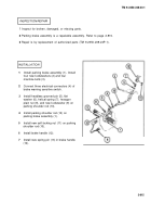
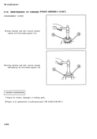
INSPECTION/REPAIR
1
Inspect for broken, damaged, or missing parts.
2
Auxiliary drive line ball bearing unit is a repairable assembly. Notify direct support
maintenance.
3
Repair is by replacement of authorized parts (TM 9-2350-238-24P-1).
2-809
Back to Top

