TM-9-2350-238-20-2 - Page 235 of 495
TM 9-2350-238-20- 2
1
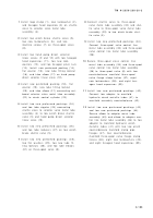
Install loop clamp (1), new lockwasher (2) ,
and hexagon head capscrew (3) on shuttl e
valve to selector valve metal tub e
assembly (4) .
2
Install tow winch brake shuttle valve (5) ,
two new Iockwashers (6), and tw o
machine screws (7) on three-spool valv e
(8) .
3
Install two hand pump direct selecto r
linear valves (9 and 10) with two hexago n
head capscrews (11), two new lock -
washers (12), and two hexagon plain nut s
(13). Install new preformed packing (14) ,
flat washer (15), new tube fitting locknu t
(16), and tube elbow (17) on hand pum p
direct selector linear valve (10) .
4
Install new preformed packing (18), fla t
washer (19), new tube fitting locknu t
(20), and tube elbow (21) connecting out -
board selector valve metal tube assembly
(22) to winch control cylinder (23) .
5
Install two new preformed packings (24 )
and two tube nipples (25) connectin g
shuttle valve to selector valve metal tub e
assembly (4) to tow winch brake shuttl e
valve (5) and hand pump direct selector
linear valve (10) .
6
Install two new preformed packings (26 )
and two tube reducers (27) on tow winc h
brake shuttle valve (5) .
7
Install two new preformed packings (28) ,
two flat washers (29), two new tube fit -
ting locknuts (30), and two tube elbow s
(31) on three-spool valve (8) .
8
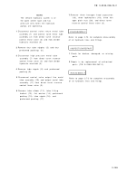
Connect shuttle valve to three-spoo l
valve metal tube assembly (32) and shut-
tle valve to three-spool valve metal tub e
assembly (33) to tow winch brake shut -
tle valve (5) .
9
Install two new preformed packings (34) .
Connect three-spool valve control lin e
metal tube assembly (35) and three-spoo l
valve control line metal tube assembly
(36) .
10
Secure three-spool valve control lin e
metal tube assembly (35) and three-spoo l
valve control line metal tube assembly
(36) to three-spool valve (8) with four
counterbalance manifold three-spoo l
valve flange clamp halves (37), eigh t
new Iockwashers (38), and eight hex -
agon head capscrews (39) .
11
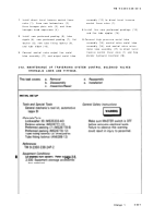
Install two new preformed packings (40) .
Connect two adapter to manifol d
hydraulic winch metallic tubes (41) t o
manifold assembly counterbalance (42) .
12
Install two new preformed packings (43 )
and two new preformed packings (44) .
Secure elbow to adapter metal tub e
assembly (45) and elbow to adapter con -
trol line metal tube assembly (46) to tw o
adapter to manifold hydraulic winc h
metallic tubes (41) with two tow winc h
counterbalance manifold clamp pip e
flanges (47), four counterbalanc e
manifold three-spool valve flange clam p
halves (48), eight new Iockwashers (49) ,
and eight hexagon head capscrews (50) .
2-19 5
Back to Top


