TM-9-2350-238-20-2 - Page 69 of 495
WARNING
TM 9-2350-238-20- 2
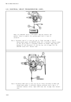
Step
5.
Place red probe on socket B (1) (GND). Ground black probe. If multimete r
indicates continuity, notify direct support maintenance for replacement o f
solenoid directional control valve (2). If multimeter indicates infinity, repair
GND lead, refer to page 2-66. Connect connector (3) .
Make sure MASTER switch is OFF before repairing electrical com-
ponents. Failure to observe this warning could result in injury t o
personnel .
Step 6 .
Disconnect lead 480 (1) from inoperative traversing circuit at rectifier (2) .
Place red probe in lead 480. Ground black probe. Set MASTER switch ON .
Set LEVEL WIND switch ON. Press sensing switch of inoperative traversin g
circuit to close. If multimeter indicates about 24 volts, replace rectifier ,
refer to page 2-271. If multimeter indicates no voltage, repair lead 480 be-
tween rectifier and sensing switch, refer to page 2-66. Set MASTER switc h
OFF. Set LEVEL WIND switch OFF. Connect lead .
2-2 9
Back to Top


