TM-9-2350-238-34-1 - Page 99 of 292
TM 9-2350-238-34-1
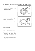
REASSEMBLY
1
2
3
4
5
6
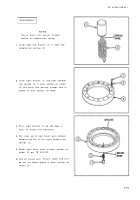
NOT E
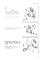
Ensure brush wire passes throug h
bottom of compression spring .
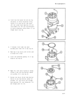
Install eight new brushes (1) in eight new
compression springs (2) .
Install eight brushes (1) and eight compres-
sion springs (2) in outer contact set holder
(3) with brush wire passing through hole in
bottom of outer contact set holder.
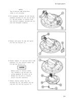
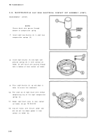
Press eight brushes (1) up and down in
holes to ensure free movement .
Pull slack out of eight brush wires without
compressing any of the eight compressio n
springs (2) .
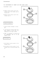
Solder eight brush wires to outer contact set
holder (3) per TB SIG-222 .
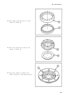
Clip off excess wire.
Ensure solder and wir e
do not rise above groove in outer contact set
holder (3) .
2-8 7
Back to Top

