TM-9-2350-256-10 - Page 204 of 796
DRIVER'S VISION ENHANCER (DVE) SENSOR ASSEMBLY INSTALLATION
1.
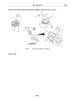
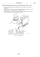
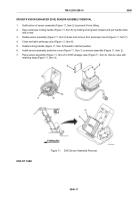
Remove retaining strap (Figure 1, Item 4) from DVE stowage case (Figure 1, Item 3).
NOTE
The interface cable should be attached. The cable stays attached to the sensor assembly
unless the sensor requires maintenance or is replaced.
2.
Open DVE stowage case (Figure 1, Item 3) and remove sensor assembly (Figure 1, Item 2).
3.
Remove protective cover (Figure 1, Item 1) from infrared window side of sensor assembly (Figure 1, Item 2)
and place in DVE stowage case (Figure 1, Item 3).
4.
Sit in operator’s seat.
5.
Ensure operator’s hatch is closed and locked (WP 0025).
6.
Unlock and open periscope door (Figure 1, Item 6) on periscope mount (Figure 1, Item 7).
7.
Open periscope-locking handle (Figure 1, Item 5) on periscope mount (Figure 1, Item 7).
8.
Turn infrared window side of sensor assembly (Figure 1, Item 2) facing front of vehicle. Place front edge of
sensor assembly in slot of periscope mount (Figure 1, Item 7) at front of periscope opening. Push up slightly
on rear and rotate periscope-locking handle (Figure 1, Item 5) forward to lock sensor assembly into place.
9.
Ensure sensor assembly (Figure 1, Item 2) is locked in center position and secure on
periscope mount (Figure 1, Item 7).
TM 9-2350-256-10
0040
0040-2
Back to Top


