TM-9-2350-256-10 - Page 208 of 796
DRIVER'S VISION ENHANCER (DVE) DISPLAY CONTROL MODULE INSTALLATION - Continued
6.
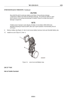
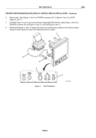
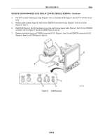
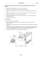
Attach power cable (Figure 4, Item 4) to POWER connector (A1J1) (Figure 4, Item 2) on DCM
(Figure 4, Item 1).
7.
Lift DCM (Figure 4, Item 1) and connect Sensor Assembly/DCM interface cable (Figure 4, Item 5) to
SENSOR connector (A1J2) (Figure 4, Item 3), on DCM (Figure 4, Item 1).
8.
Rotate DCM (Figure 4, Item 1) upward and insert into mounting slots located on front and just below
operator's hatch opening. Ensure both retaining pins lock in place.
Figure 4.
DCM Installation.
TM 9-2350-256-10
0040
0040-6
Back to Top

