TM-9-2350-256-10 - Page 56 of 796
HYDRAULIC SYSTEMS
•
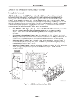
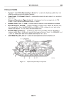
Operator’s Control Valve Manifold (Figure 12, Item 1)
— contains the directional control valves that
allow the operator to control the hydraulic systems.
•
Power Takeoff (PTO) (Figure 12, Item 2)
— mechanically connects the main engine to the mechanical
transmission.
•
Mechanical Transmission (Figure 12, Item 3)
— directs power from the main engine via the PTO
(Figure 12, Item 2) to the hydraulic pump (Figure 12, Item 4).
•
Hydraulic Pump (Figure 12, Item 4)
— provides hydraulic pressure to operate the hydraulic system.
•
Hoist Winch (Figure 12, Item 5)
— capable of handling a maximum load of 25 tons (22.68 metric tons)
with a four part line. Wound with 200 ft (60.96 m) of 0.625-in. (15.88-mm) diameter steel cable with a
useable cable length of 175 ft (53.34 m). Use with hoisting boom.
•
Main Winch (Figure 12, Item 6)
— used for heavy-duty recovery operations. Capable of winching a
maximum load of 45 tons (40.82 metric tons) with four wraps on the drum. Wound with 200 ft (60.96 m) of
1.25-in. (31.75-mm) steel cable with a useable cable length of 174 ft (53 m).
•
Level Winder (Figure 12, Item 7)
— controls the cable placement on the main winch drum.
Figure 12.
Hydraulic System Major Components.
TM 9-2350-256-10
0003
0003-14
Back to Top

